High NA single-objective light-sheet
This project is maintained by amsikking in the York lab, and was funded by Calico Life Sciences LLC
Appendix
Note that this is a limited PDF or print version; animated and interactive figures are disabled. For the full version
of this article, please visit one of the following links:
https://andrewgyork.github.io/high_na_single_objective_lightsheet
High NA single-objective light-sheet
Design
Build
Parts list - emission path
This table can be used as a shopping list for the original design of the emission path. For clarity, the elements are listed in order in which they are physically arranged (from sample to camera). All of the optics are 'stock' parts except for items 10 (O2*) and 11 (O3) which are currently 'bespoke'. Item 10, the small glass window (O2*), can be exchanged for a standard coverslip for limited budgets. If you are interested in item 11 the glass-tipped objective (O3) then please see the following section on the AMS-AGY objective v1.0.
| Item number (ID) | Supplier | Part | Description | Qty |
|---|---|---|---|---|
| 1 (S) | Biologist | Sample | preferred with typical live cell refractive index: 1.35 to 1.4 | 1 |
| 2 (O1) | Nikon | MRD73950 | CFI SR HP Plan Apo Lambda S 100XC Sil | 1 |
| 3 (TL1) | Nikon | MXA22018 | Tube lens, EFL=200 mm | 1 |
| 4 (SL1) | Thorlabs | CLS-SL | Scan lens, EFL=70 mm | 1 |
| 5 (G1) | Thorlabs | GVS201 | 1D Galvo system, ∅5 mm | 1 |
| 6 (SL2) | Thorlabs | LSM03-VIS | Scan lens, EFL=39 mm | 1 |
| 7 (TL2) | Nikon | MXA22018 | Tube lens, EFL=200 mm | 1 |
| 8 (D) | Chroma | ZT405/488/561/640rpcv2 | Quad band dichroic (excitation coupling) | 1 |
| 9 (O2) | Nikon | MRD00405 | CFI Plan Apo Lambda 40XC | 1 |
| 10 (O2*) | Mark Optics | N/A | NBK-7 window, OD:(4 +/- 0.2) mm, Thk:(0.170 +/- 0.0127) mm, TWE:1/4 wave, parallelism:<10 μm, polished:40/20 and coated:Tavg >99%, (400-700) nm @ 0° AOI both sides | 1 |
| 11 (O3) | ASI | AMS-AGY v1.0 | Special glass-tipped objective | 1 |
| 12 (E) | Chroma | ZET405/488/561/640m | Quad emission filter, ∅25 mm mounted | 1 |
| 13 (TL3) | Nikon | MXA22018 | Tube lens, EFL=200 mm | 1 |
| 14 (C) | PCO | edge 4.2 | sCMOS camera, 2048x2048 pixels with 6.5x6.5 μm2 size | 1 |
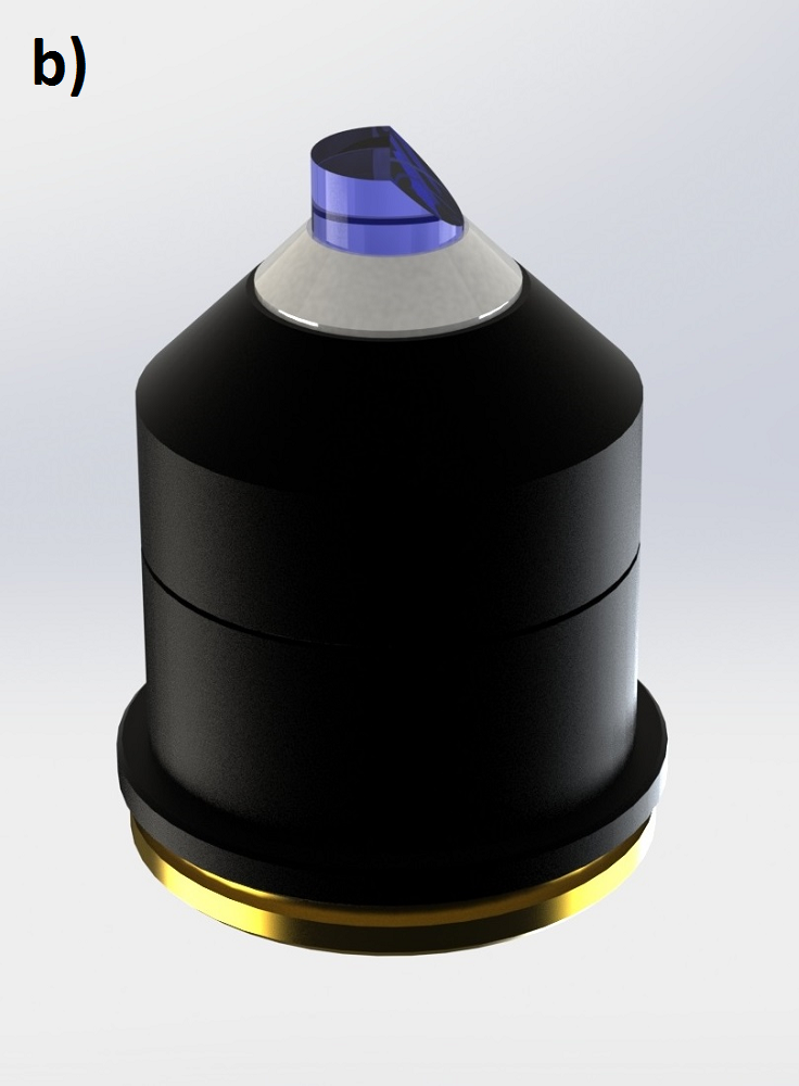
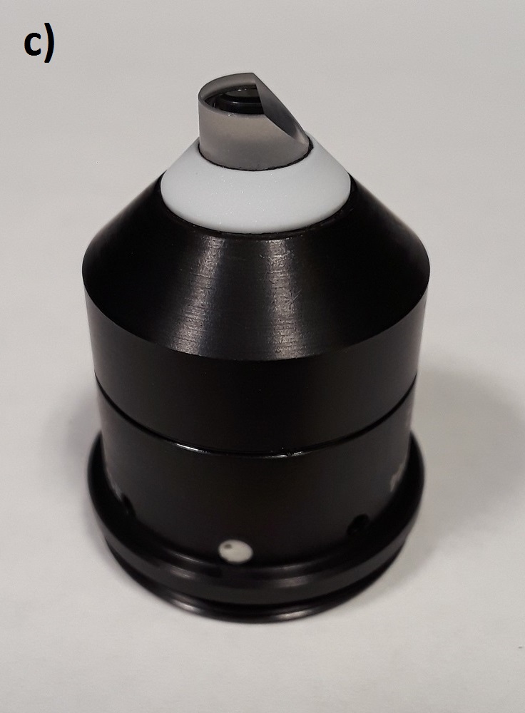
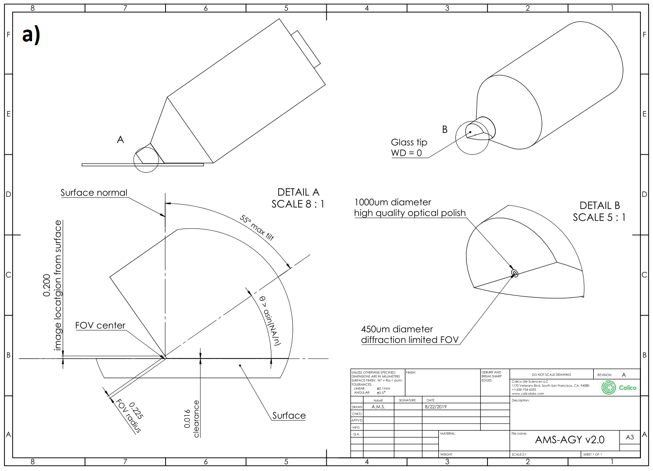
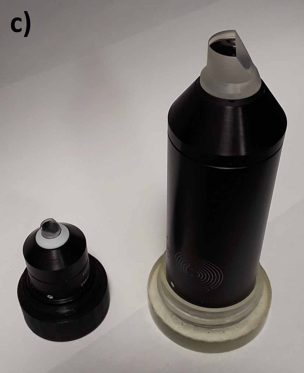
AMS-AGY objective - v1.0
The critical enabling component of the high NA single-objective light-sheet microscope is the bespoke glass-tipped objective. By choosing all stock parts throughout the design of the rest of the microscope many of the opto-mechanical difficulties are compressed into the design of this final objective (Figure A1). The optical performance and geometry of this lens allow it to extract a high resolution image as close as ~100 μm to a flat surface, with negligible loss in resolution and high transmission, over a range of tilt angles from 0-45 degrees.
If you are interested in acquiring one of the AMS-AGY objectives then please contact Jon Daniels at Applied Scientific Imaging (ASI) directly: jon@asiimaging.com (or info@asiimaging.com).
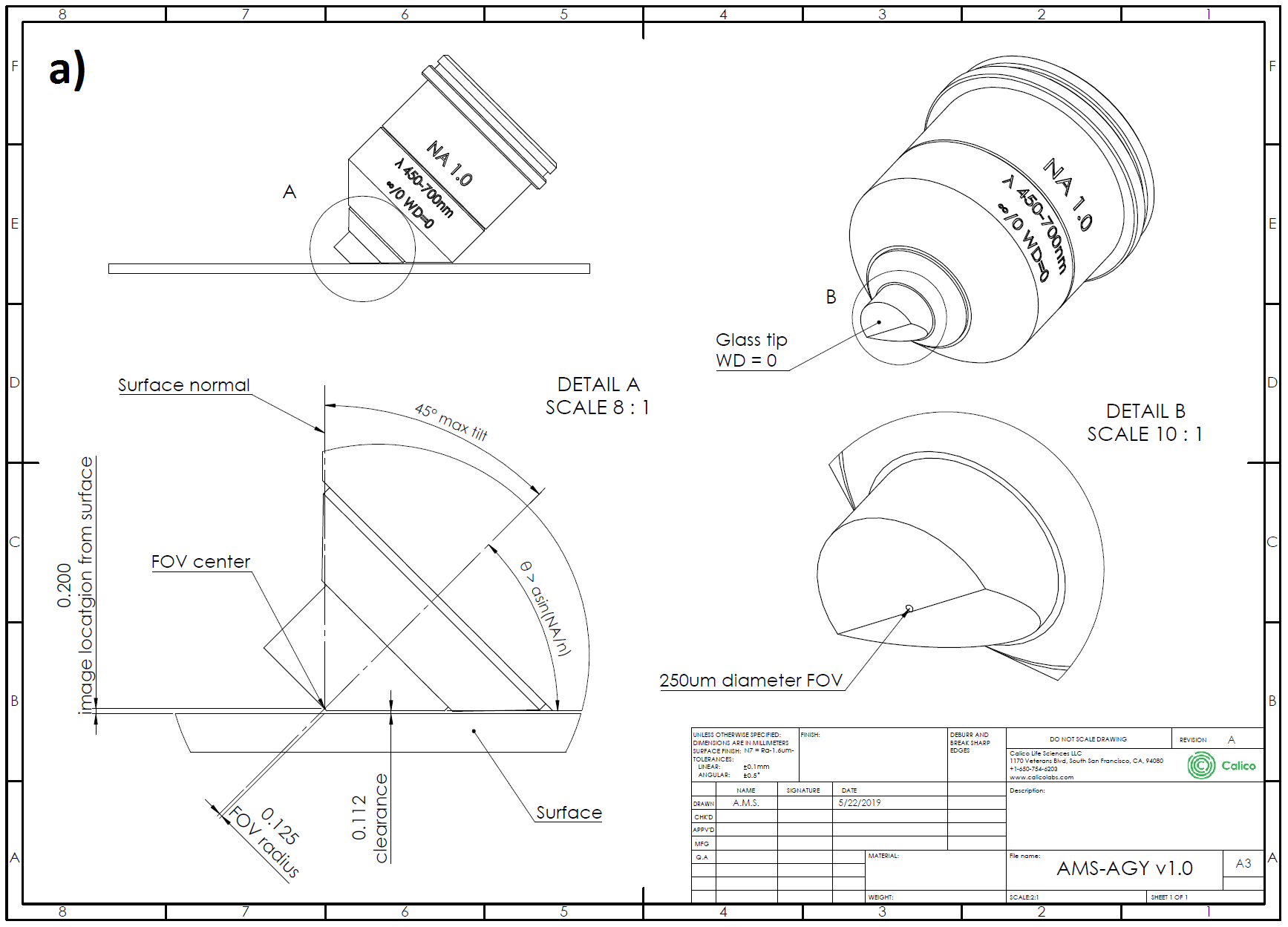
The AMS-AGY v1.0 optical specifications are as follows:
| Specification | Description |
|---|---|
| NA = 1.0 | numerical aperture |
| ∞/0 | infinity corrected / coverslip thickness |
| WD = 0 | working distance |
| EFL = 5 mm | effective focal length (e.g. 40x with 200 mm tube lens) |
| λ = 450-700 nm | color correction |
| FOV (DL) = ∅150 μm | diffraction limited field of view diameter |
| FOV (bevel) = ∅250 μm | mechanically limited field of view diameter (1 direction only) |
AMS-AGY objective - v2.0
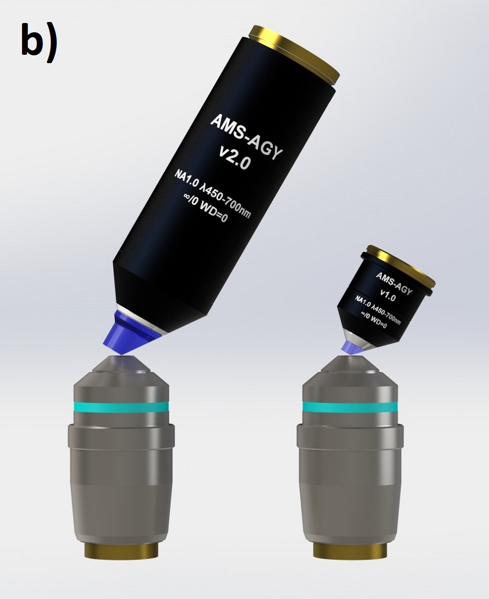
The AMS-AGY v2.0 optical specifications are as follows:
| Specification | Description |
|---|---|
| NA = 1.0 | numerical aperture |
| ∞/0 | infinity corrected / coverslip thickness |
| WD = 0 | working distance |
| EFL = 9 mm | effective focal length (e.g. 22.22x with 200 mm tube lens) |
| λ = 450-700 nm | color correction |
| FOV (DL) = ∅450 μm | diffraction limited field of view diameter (> ∅750 μm usable) |
| FOV (bevel) = ∅450 μm | mechanically limited field of view diameter (1 direction only) |
Align
Alignment goals
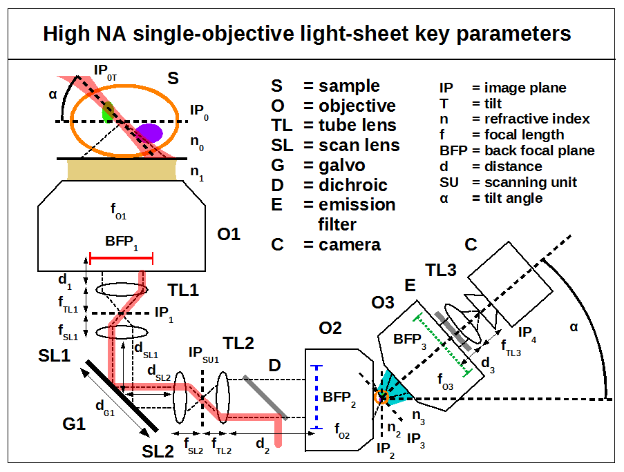
Here we recommend alignment goals for good performance. This is not a detailed alignment procedure but should be sufficient for an experienced builder and is applicable to all the optical configurations. With reference to the SOLS parameters figure try to achieve the following:
- XY and tip/tilt alignment: The primary objective (O1) sets the optical axis of the system. Each subsequent lens must then be aligned so that its optical axis is co-linear with the primary axis. In systems that include one or more galvos, the clear aperture of each galvo mirror should be roughly centred on the optical axis (to avoid clipping), and the rotation axis of each galvo should intersect and be perpendicular to the optical axis (as is typically done). This defines the xy (translation) and tip/tilt (rotation) of each element. A laser beam can be a useful reference to indicate the optic axis and the position of optics relative to this axis (see for example Appendix E of [Abrahamsson 2015].
- Z alignment: Wherever possible, our designs use lens pairs that are axially separated so that they conserve collimation. i.e. for any consecutive pair of lenses a collimated beam input should give a collimated beam output. This simple guideline defines the z position of each lens once the primary objective position has been fixed. Galvo mirrors should be imaged to the back focal plane of the primary objective (BFP1) so that a rotation of the mirror results in a pure translation in the image space (true for small angles).
- Commercial bases: When using a commercial base it is typical that the primary objective (O1) and the first tube lens (TL1) do not conserve collimation (usually the tube lens is too close). This can be corrected by adjusting the separation between the next two lenses, SL1 and SL2 (or TL2 and O2 for systems with no galvo) to achieve the following conditions:
- Tube lens TL1 and the next lens SL1 (or TL2 for systems with no galvo) preserve collimation.
- The primary objective (O1), the primary tube lens (TL1) and the next two lenses, SL1 and SL2 or (TL2 and O2 for systems with no galvo) together preserve collimation.
- The following equations describe the required displacement for each case and can be used as a guide of magnitude (in practice the correct displacement must be found by aligning with an appropriate laser beam):
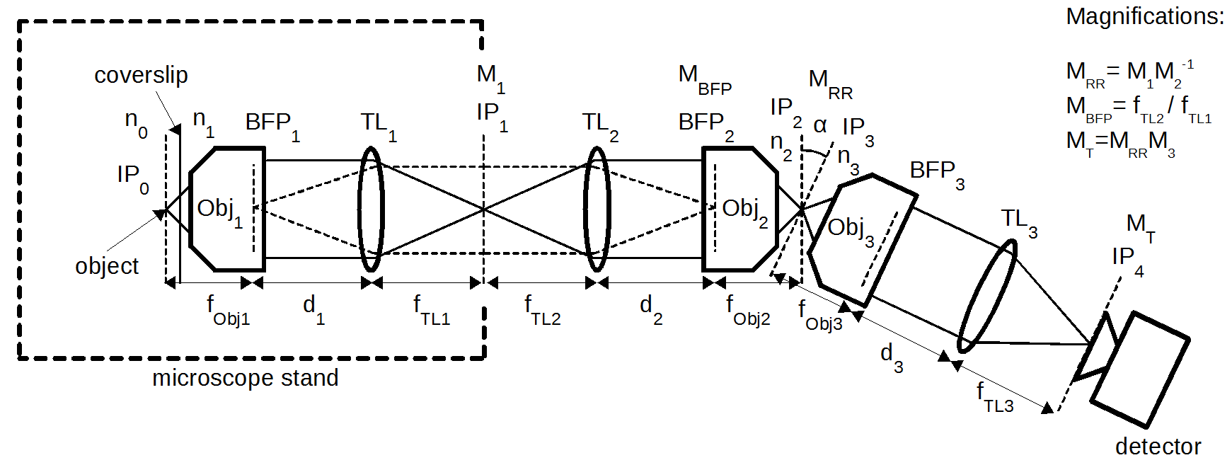
- No galvo: \( d_2 = f_{TL2} + (f_{TL1} - d_1)M_{BFP_{1}}^2 \) where \( M_{BFP1} = f_{TL2} / f_{TL1} \)
- With galvo(s): \( d_{SL1} = f_{SL1} + (f_{TL1} - d_1)M_{BFP1}^2 \) where \( M_{BFP1} = f_{SL1} / f_{TL1} \)
- Back focal plane mapping: if the preceding goals are achieved then the back focal plane of the primary objective (BFP1) will be effectively imaged throughout the system i.e. BFP1 to G1, G1 to BFP2 and BFP2 to BFP3 (and the same concept applies with no-galvo or 2-galvo/4-SL systems). We highlight this goal as it is similar to relaying the image planes IP0 through to IP4 but with more subtle (but still significant) consequences if not done sufficiently well. Error in image plane alignment is usually obvious from the resulting defocus. Error in BFP relay can be more tricky to notice and result in the following symptoms:
-
- Error in BFP1 to galvo: can result in angular motion coupled to what should be a pure translation of the image plane. This can modulate the tilt of the light-sheet as a function of scan and confuse the image processing and interpretation of data.
- Error in BFP1 to BFP2: an easy mistake if one is not careful during alignment, and can result in clipping the image of BFP1 at BFP2. The result is reduced effective numerical aperture and compromised remote refocus performance. If the point spread function measurements are good at IP1 and disappointing in the remote space at IP2 then be sure to check this alignment.
- Error in BFP2 to BFP3: also easy to do if not careful during alignment and also results in reducing the effective numerical aperture of the system. If the point spread function measurements are good in the remote space at IP2 and disappointing at IP4 then be sure to check this alignment.
- Note: if O1 has a z range (e.g. ~10 mm on a commercial base) then for best performance it should be set to its nominal focal position (for the intended samples) during alignment.
- Light-sheet coupling and tilt angle '\( \alpha \)': any given light-sheet should be coupled into the primary objective (O1) so that its marginal ray is coincident with the marginal ray of the objective (i.e. the edge of the light-sheet should touch the maximum collection cone angle of the objective). For a given choice of light-sheet the third microscope system should then be tilted so that the light-sheet is uniformly in focus. There are many choices of primary objective and many light-sheet options which together will determine the resulting tilt angle \( \alpha \), and so an exact alignment target cannot be set without further specifying the system. However, by following this basic alignment protocol unnecessary losses in resolution and efficiency can be avoided.
- Galvo flatness: is your galvo flat enough? If you have achieved the above alignment goals and are getting weird PSF results then check the galvo flatness (for example using a shearing interferometer). If you want to buy your way out of this potential problem then specify better than λ/10 PV or λ/14 RMS over the aperture (image of BFP1 at the galvo).
Optical configurations
Several of our colleagues have expressed interest in modified versions of our reference design. We think this is wonderful, but we've already noticed pitfalls and mistakes that are commonly encountered (but easily avoided). It's critical to use lenses that give the right magnifications, and avoid aberrations and vignetting. Here we offer a selection of alternative configurations for high NA single-objective light-sheets. We haven't built these versions, but based on our knowledge and experience we expect them to have excellent performance (comparable to our reference design). Please try them and give us feedback - we are here to help and if you want to roll your own design, feel free to reach out - some low-effort advice from us might save you a lot of time and money. See the following guide on how to configure your own single-objective light-sheet microscope.
Configuration guide
- Pick a primary objective (O1): use the table below to select a primary objective based on the intended sample type. With O1 selected we recommend using the corresponding manufacturer's tube lens (TL1) for commercial base compatibility. Now select a remote refocus module by choosing one of our recommended secondary objectives (O2) and corresponding tube lenses (TL2). Note: this choice is independent from the base microscope, for example a Nikon base (O1 + TL1) can be matched with an Olympus remote refocus (O2 + TL2). We have configured the systems this way for maximum flexibility, and designed a series of low cost tube lens assemblies to solve some of the optical challenges (labelled as EFLxxx in the tables below).
Oil immersion with coverslip:
| Primary objective (O1 + TL1) | Secondary objective (O2 + TL2) |
|---|---|
| Nikon 60x1.4 Oil (MRD01605 + MXA22018) or Olympus 60x1.42 Oil (UPLXAPO60XO + SWTLU-C) |
Nikon 40x0.95 (MRD00405 + MXA22018) or Olympus 40x0.95 (UPLXAPO40X + SWTLU-C) |
Silicone immersion with coverslip:
| Primary objective (O1 + TL1) | Secondary objective (O2 + TL2) |
|---|---|
| Nikon 100x1.35 Sil (MRD73950 + MXA22018) or Olympus 100x1.35 Sil (UPLSAPO100XS + SWTLU-C) |
Nikon 40x0.95 (MRD00405 + EFL357) or Olympus 40x0.95 (UPLXAPO40X + EFL321 |
| Olympus 60x1.3 Sil (UPLSAPO60XS2) + (SWTLU-C) | Nikon 40x0.95 (MRD00405 + EFL214) or Olympus 40x0.95 (UPLXAPO40X + EFL193) |
| Nikon 40x1.25 Sil (MRD73400 + MXA22018) or Olympus 40x1.25 Sil (UPLSAPO40XSS + SWTLU-C) |
Nikon 40x0.95 (MRD00405 + EFL143) or Olympus 40x0.95 (UPLXAPO40X + EFL129) |
| Olympus 30x1.05 Sil (UPLSAPO30XS + SWTLU-C) | Nikon 20x0.75 (MRD00205 + EFL214) or Olympus 20x0.8 (UPLXAPO20X + EFL193) |
| Nikon 25x1.05 Sil (MRD73250 + MXA22018) | Nikon 20x0.75 (MRD00205 + EFL179) or Olympus 20x0.8 (UPLXAPO20X + EFL161) |
Water immersion with coverslip:
| Primary objective (O1 + TL1) | Secondary objective (O2 + TL2) |
|---|---|
| Nikon 60x1.27 W (MRD07650 + MXA22018) or Olympus 60x1.2 W (UPLSAPO60XW + SWTLU-C) |
Nikon 40x0.95 (MRD00405 + EFL226) or Olympus 40x0.95 (UPLXAPO40X + EFL203) |
| Nikon 40x1.15 W (MRD77410 + MXA22018) or Olympus 40x1.15 W (UAPON40XW340 + SWTLU-C) |
Nikon 40x0.95 (MRD00405 + EFL150) or Olympus 40x0.95 (UPLXAPO40X + EFL135) |
Water dipping:
| Primary objective (O1 + TL1) | Secondary objective (O2 + TL2) |
|---|---|
| Nikon 25x1.1 W (MRD77220 + MXA22018) or Olympus 25x1.05 W (XLPLN25XWMP2 + SWTLU-C) |
Nikon 20x0.75 (MRD00205 + EFL188) or Olympus 20x0.8 (UPLXAPO20X + EFL169) |
| Olympus 20x1.0 W (XLUMPLFLN20XW + SWTLU-C) | Nikon 20x0.75 (MRD00205 + EFL150) or Olympus 20x0.8 (UPLXAPO20X + EFL135) |
- Pick 0, 1 or 2 galvo scanners: As a default we recommend using 1 galvo scanner; for further discussion see the design options section. For those who want to use a galvo scanner the following (unity magnification) relay is a good place to start:
| Scan lens 1 (SL1) | Galvo 1 (G1) | Scan lens 2 (SL2) |
|---|---|---|
| Thorlabs 70 mm (CLS-SL) | Thorlabs ∅5 mm (GVS201) or Thorlabs ∅10 mm (GVS211) |
Thorlabs 70 mm (CLS-SL) |
Galvo scanner considerations:
- Magnification: for our configurations to work the galvo scanner must be a unity magnification relay:
- \( f_{SL2}/f_{SL1} = 1 \)
- Scan lens performance: make sure your scan lenses are capable of handling the scan pupil diameter, the diameter of the field of view and color range you want to accommodate. By scan pupil diameter (\( d_{scan \; pupil}\)) we mean the diameter of the image of BFP1 after SL1:
- \( d_{scan \; pupil} = 2 f_{O1} NA_1 (f_{SL1}/f_{TL1}) \) where \( f_{O1} = f_{TL \; man}/M_1 \)
- (and \(NA_1\) and \(M_1\) are the numerical aperture and magnification of O1, and \(f_{TL \; man}\) is the focal length of the manufacturers tube lens of O1).
- \(d_{field} = d_{IP_1} \) (O1 field number if using the manufacturers tube lens for TL1).
- ∅26 mm field diameter, ∅2.5 mm scan pupil diameter
- ∅22 mm field diameter, ∅3 mm scan pupil diameter
- ∅16 mm field diameter, ∅4 mm scan pupil diameter
- ∅13 mm field diameter, ∅5 mm scan pupil diameter
- ∅11 mm field diameter, ∅6 mm scan pupil diameter
- ∅9 mm field diameter, ∅7 mm scan pupil diameter
- Galvo size: to avoid clipping the scan pupil, make sure the galvo diameter is large enough:
- \(d_{G1} \geq \sqrt{2} \, d_{scan \; pupil} \) (for a 90 degree fold)
Note: galvo mirrors are typically thin so they are light and fast to rotate. As the mirror diameter increases it becomes harder to maintain flatness which can seriously degrade optical performance. If you want to buy your way out of this potential problem then specify better than λ/10 PV or λ/14 RMS for the mirror.
- Pick a camera: we recommend a high quantum efficiency (QE), low read noise sCMOS chip if your budget allows. For example the PCO edge 4.2 is a fine choice for most configurations. Consider the following when selecting a camera:
- Pixel number: The AMS-AGY v1.0 objective can deliver ∅150 μm of diffraction limited field and up to ∅250 μm at lower performance. For Nyquist sampling at λavg ~ 0.55 μm this equates to ~900 pixels of the highest quality and up to ~1500 pixels where imaging is still very good:
- \( n_{pixels} \approx 2 \, d_{IP_3} NA_3 / (0.61\lambda)\)
(\(NA_3 = 1.0 \) for the AMS-AGY objective)
- \( n_{pixels} \approx 2 \, d_{IP_3} NA_3 / (0.61\lambda)\)
- Pixel size: The AMS-AGY v1.0 objective has a 5 mm effective focal length. The last tube lens TL3 can be used as a free parameter to tune the magnification for Nyquist:
- \( f_{TL3} \approx 2 f_{O3} \, d_{pixel} NA_3 / (0.61\lambda) \)
Example: Nikon 40x(1.15) water with coverslip
'I want to do expansion microscopy on relatively large (aqueous) samples at high resolution. The samples are weakly flourescent so I want to use light sheet with minimal optics on the emission path. Speed is not important to me. I have a Nikon base already and I can borrow an Olympus objective from a collaborator for O2.'
System notes:
For maximum optical efficiency galvo/scan lens relays will not be used on this system; instead the sample will be scanned at a significantly slower rate. The only limits on sample size will be the relatively large working distance of the primary objective (~600 μm here). An AR coated window will be used at O2* for maximum transmission. A galvo scanner can be added later if sample scanning proves too slow.
Optical train:
| Item ID | Supplier | Part | Description | Qty |
|---|---|---|---|---|
| S | Biologist | Sample | expanded samples, refractive index: ~1.33 | 1 |
| O1 | Nikon | MRD77410 | 40x(1.15) water through coverslip, W.D. 0.59-0.61 mm, 22 mm field | 1 |
| TL1 | Nikon | MXA22018 | Tube lens, EFL=200 mm | 1 |
| TL2 | Thorlabs | EFL135 | Tube lens assembly, EFL=135 mm | 1 |
| D | Chroma | ZT405/488/561/640rpcv2 | Quad band dichroic (excitation coupling) | 1 |
| O2 | Olympus | UPLXAPO40X | 40x0.95 CFI Plan Apo Lambda | 1 |
| O2* | Mark Optics | custom | NBK-7 window, OD:(10 +/- 0.2) mm, Thk:(0.170 +/- 0.05) mm, TWE:1/4 wave, parallelism:<10 μm, polished:40/20 and coated:Tavg >99%, (400-700) nm @ 0° AOI both sides | 1 |
| O3 | ASI | AMS-AGY v1.0 | Special glass-tipped objective | 1 |
| E | Chroma | ZET405/488/561/640m | Quad emission filter, ∅25 mm mounted | 1 |
| TL3 | Nikon | MXA22018 | Tube lens, EFL=200 mm | 1 |
| C | PCO | edge 4.2 | sCMOS camera, 2048x2048 pixels with 6.5x6.5 μm2 size | 1 |
Example: Olympus 20x(1.0) water dipping
'I work with Zebrafish so I'm looking for a water dipping system with a large field of view and long working distance. I already have an Olympus 20x1.0 dipping lens, a Nikon 20x0.75 from another system and a limited budget. Field of view and speed are most important for my application so I'm going to choose a two-galvo system to maximise the data rate on my sCMOS camera and I'm willing to sacrifice some optical performance.'
System notes:
- \( d_{BFP_1} = 2*180*(1/20) = 18 \, mm\)
- \(d_{scan \; pupil} = 18*(70/180) = 7 \, mm \)
- \(d_{G1} \geq \sqrt{2} \, d_{scan \; pupil} = 9.9 \, mm \)
- The 7 mm scan pupil is large for the CLS-SL scanning relay so the diffraction limited field will be about 9 mm at IP1 (or about 450 μm in the sample) but it will still image up to 22 mm at lower performance (which is the field number of the primary objective). A 10 mm galvo is large enough for the pupil, but this is quite a big mirror so I should check flatness. I'm going to use a standard 25 mm coverslip to correct O2 to save on cost. I'll upgrade my scanning system later with large field scan lenses when I have the budget (for example contact Special Optics for a tailored solution).
Optical train:
| Item ID | Supplier | Part | Description | Qty |
|---|---|---|---|---|
| S | Biologist | Sample | Zebrafish in water, refractive index: ~1.33 | 1 |
| O1 | Olympus | XLUMPLFLN20XW | 20x(1.0) water dipping, W.D. = 2 mm, 22 mm field | 1 |
| TL1 | Olympus | SWTLU-C | Tube lens, EFL=180 mm | 1 |
| SL1 | Thorlabs | CLS-SL | Scan lens, EFL=70 mm | 1 |
| G1 | Thorlabs | GVS211 | 1D scan galvo, ∅10 mm | 1 |
| SL2 | Thorlabs | CLS-SL | Scan lens, EFL=70 mm | 1 |
| SL3 | Thorlabs | CLS-SL | Scan lens, EFL=70 mm | 1 |
| G2 | Thorlabs | GVS211 | 1D tile galvo, ∅10 mm | 1 |
| SL4 | Thorlabs | CLS-SL | Scan lens, EFL=70 mm | 1 |
| TL2 | Thorlabs | EFL150 | Tube lens assembly, EFL=150 mm | 1 |
| D | Chroma | ZT405/488/561/640rpcv2 | Quad band dichroic (excitation coupling) | 1 |
| O2 | Nikon | MRD00205 | 20x0.75 CFI Plan Apo Lambda | 1 |
| O2* | Various | N/A | Coverslip, OD: ~25 mm, Thk:(0.170 +/- 0.05) mm | 1 |
| O3 | ASI | AMS-AGY v1.0 | Special glass-tipped objective | 1 |
| E | Chroma | ZET405/488/561/640m | Quad emission filter, ∅25 mm mounted | 1 |
| TL3 | Nikon | MXA22018 | Tube lens, EFL=200 mm | 1 |
| C | PCO | edge 4.2 | sCMOS camera, 2048x2048 pixels with 6.5x6.5 μm2 size | 1 |
Tube lens assemblies
One of the challenges of designing a single-obective light-sheet is making a good remote refocus (detailed in our previous work). For an air based remote refocus a key requirement is to match the magnification of the remote image to the refractive index of the primary objective. As the primary objective changes, often the magnification and refractive index also change, which can make it awkward to find the right set of optics. We solve this by creating a series of low cost tube lens assemblies at convenient focal lengths to enable builders to configure the microscope as they wish. See the table and figure below to build your own tube lens assembly:
| TL2 assembly | Optical components (part#) |
|---|---|
| EFL129 | Thorlabs (TTL200MP) + 2x (AC508-500-A) |
| EFL135 | Thorlabs (TTL200MP) + (AC508-750-A) + (AC508-500-A) |
| EFL143 | Thorlabs (TTL200MP) + (AC508-750-A) + (AC508-500-A) |
| EFL150 | Thorlabs (TTL200MP) + 2x (AC508-750-A) |
| EFL161 | Thorlabs (TTL200MP) + 2x (AC508-1000-A) |
| EFL169 | Thorlabs (TTL200MP) + (AC508-750-A) |
| EFL179 | Thorlabs (TTL200MP) + (AC508-1000-A) or Olympus (SWTLU-C) |
| EFL188 | Thorlabs (TTL200MP) + (AC508-1000-A) |
| EFL193 | Thorlabs (TTL200MP) + (AC508-1000-A) |
| EFL203 | Thorlabs (TTL200MP) + (LF-1141-A) or Nikon (MXA22018) |
| EFL214 | Thorlabs 3x (AC508-750-A) + (AC508-1000-A) |
| EFL226 | Thorlabs 3x (AC508-750-A) + (AC508-1000-A) |
| EFL321 | Thorlabs (AC508-750-A) + (AC508-500-A) |
| EFL357 | Thorlabs (AC508-750-A) + (AC508-500-A) |
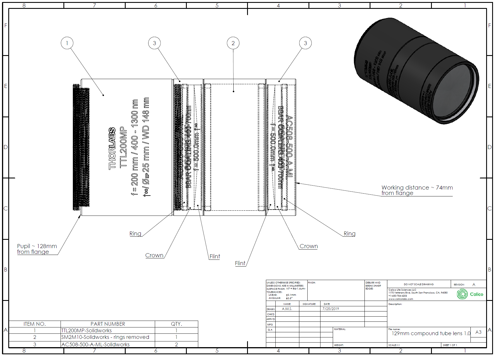
| Tube lens option = | the last 3 numbers indicate the effective focal length (mm) |
Theoretical performance
In the abstract we claim that we "sacrifice no appreciable numerical aperture". The figure below illustrates what we mean by this:
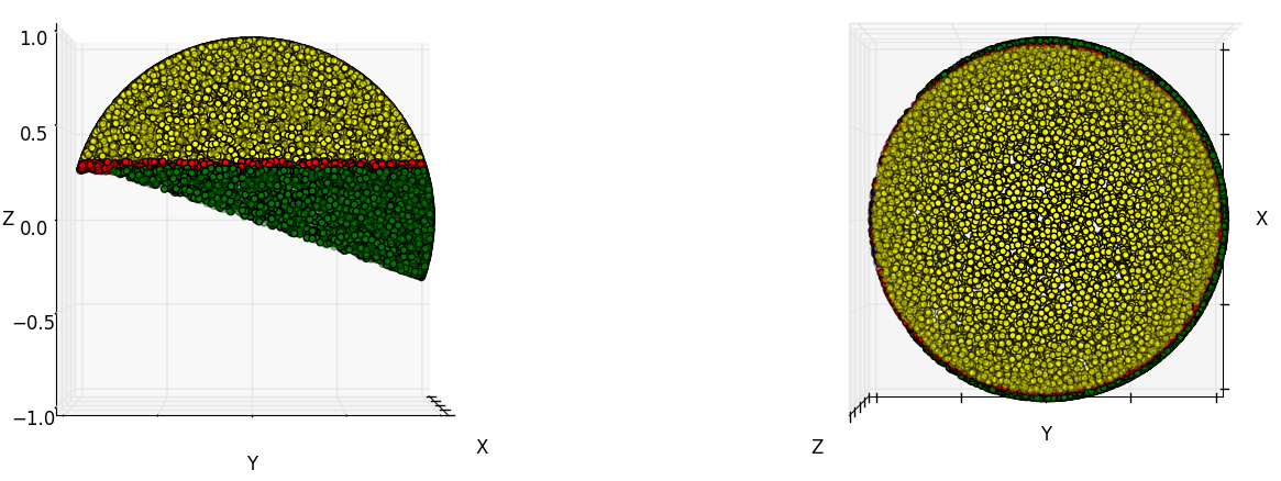
Each yellow dot on the surface of the illustrated sphere represents a ray angle that can propagate from a point source in the sample, through our three objective lenses, and reach our detector. Each red dot indicates a ray that is collected by our primary objective (1.35 NA silicone), but clipped by our secondary objective (0.95 NA air). Each blue dot represents a ray which passes our secondary objective, but is clipped by our tertiary objective (note that there are almost no blue dots). Each green dot indicates a ray that our tertiary objective (1.0 NA glass) could have collected, if the secondary objective produced it. In our primary design, >95% of the rays collected by objective 1 can pass objective 2, and >99% of the rays collected by objective 2 can pass objective 3, giving an effective NA of about 1.33. See the code below used to calculate these quantities:
#!/usr/bin/python3
import numpy as np

# Three spherical caps: 1 and 2 are centered on the z-axis, 3 is pi
# radians wide
cap_1_width = np.arcsin(1.35/1.404) # radians
cap_2_width = np.arcsin(0.95)       # radians
sheet_half_angle = 3 * np.pi/180    # radians
cap_3_tilt = (np.pi/2 - cap_1_width) + sheet_half_angle # radians, in yz plane
# Generate random points on the surface of a sphere
num_points = int(3e4)
phi = np.random.uniform(0, 2*np.pi, num_points)
theta = np.arccos(np.random.uniform(-1, 1, num_points))
# Calulate z in a rotated frame where cap 2 is centered on the (new) z-axis:
z_rotated = (np.sin(cap_3_tilt) * np.sin(theta) * np.sin(phi) +
             np.cos(cap_3_tilt) * np.cos(theta))
# Check which caps each point occupies:
in_cap_1 = theta < cap_1_width
in_cap_2 = theta < cap_2_width
in_cap_3 = z_rotated > 0
# Estimate the fraction of the first cap covered by the second and third caps
ratio_1_2 = (np.count_nonzero(in_cap_1 & in_cap_2) /
             np.count_nonzero(in_cap_1))
ratio_2_3 = (np.count_nonzero(in_cap_2 & in_cap_3) /
             np.count_nonzero(in_cap_2))
print("Spherical cap 1 half-angle: %0.3fpi radians (%0.2f degrees)"%(
    cap_1_width / np.pi, cap_1_width * 180/np.pi))
print("Spherical cap 2 half-angle: %0.3fpi radians (%0.2f degrees)"%(
    cap_2_width / np.pi, cap_2_width * 180/np.pi))
print("Spherical cap 3 tilt angle: %0.3fpi radians (%0.2f degrees)"%(
    cap_3_tilt / np.pi, cap_3_tilt * 180/np.pi))
print("Fraction of cap 1 covered by cap 2: %0.5f"%(ratio_1_2))
print("Fraction of cap 2 covered by cap 3: %0.5f"%(ratio_2_3))
Note that our number for "efficiency" is fairly sensitive to how we define efficiency. For example, if objective 1 were 1.33 NA rather than 1.35 NA, then >99% of the rays collected by the primary can also pass the secondary and tertiary objectives. In our experience, rays at the very edge of the primary objective NA are somewhat aberrated, and do not contribute to improved resolution. We often take pains to differentiate between specified NA (rays which are collected) and useful NA (rays which contribute to improved resolution); our design captures >99% of our primary objective's useful NA. Note also that if a 0.96 NA air objective ever became available, we could substitute it as the secondary objective and collect >99% of the primary objective's specified 1.35 NA rays.
Archive
We use this section to store previous sections of the publication that have since been replaced in some way or are no longer appropriate for the main article.
(Deprecated) Alternative optical configurations
(Deprecated) Nikon 100x NA 1.35 - stage or piezo scanning solution
For those who don't want or need galvo scanning. This design has fewer optics for a system with lower cost, higher efficiency and easier maintenance. It could be a good option for high content screening systems that use stage scannning, or systems that use a piezo on the second objective to take volumes (or a combination of both)
| Item # | Supplier | Part | Description | Qty |
|---|---|---|---|---|
| 3 | Thorlabs | TTL165-A | Tube Lens, f = 165 mm, ARC: 350-700 nm, External SM2 Threads (NOTE: this is not a Zeiss OEM tube lens) | 1 |
| 4-6 | N/A | N/A | Galvo scanning relay removed. | 0 |
| 7 | Thorlabs | TL300-A | Laser Scanning Tube Lens, f = 300 mm, ARC: 400 - 700 nm | 1 |
(Deprecated) Olympus 60x NA 1.3 - galvo scanning solution
This is a high quality primary objective used by many labs - we expect this version to be popular.
| Item # | Supplier | Part | Description | Qty |
|---|---|---|---|---|
| 2 | Olympus | UPLSAPO 60xS2 | Super Apochromat, 60x Silicone Oil Immersion Objective Lens, N.A. 1.3, W.D. 0.3 mm, F.O.V. 22 mm, DIC, Correction Collar 0.15-0.19 mm | 1 |
| 3 | Thorlabs | TL300-A | Laser Scanning Tube Lens, f = 300 mm, ARC: 400 - 700 nm | 1 |
(Deprecated) Olympus 60x NA 1.3 - stage or piezo scanning solution
For those who don't want or need galvo scanning.
| Item # | Supplier | Part | Description | Qty |
|---|---|---|---|---|
| 2 | Olympus | UPLSAPO 60xS2 | Super Apochromat, 60x Silicone Oil Immersion Objective Lens, N.A. 1.3, W.D. 0.3 mm, F.O.V. 22 mm, DIC, Correction Collar 0.15-0.19 mm | 1 |
| 3 | Thorlabs | TTL165-A | Tube Lens, f = 165 mm, ARC: 350-700 nm, External SM2 Threads (this is not a Zeiss OEM tube lens) | 1 |
| 4-6 | N/A | N/A | Galvo scanning relay removed. | 0 |
| 7 | Olympus | SWTLU-C | 180 mm focal length, tube lens unit. | 1 |
| 9 | Olympus | UPLSAPO 40x2 | Super Apochromat, 40x Objective Lens, N.A. 0.95, W.D. 0.18 mm, F.O.V. 26.5 mm, Correction Collar 0.11-0.23 mm | 1 |
(Deprecated) Focus on Microscopy 2019 - Abstract
"A BOLT-ON SINGLE-OBJECTIVE LIGHT-SHEET DESIGN WITH UNCOMPROMISED NUMERICAL APERTURE"
Spinning disk confocal modules are “core facility friendly”; they insert conveniently between a commercial microscope base and camera, improve image quality and add no significant drawbacks. In contrast, high numerical aperture (NA) light sheet microscopy often requires radical sample modification, substantial user re-training and fully customized hardware. We present a “core-facility friendly” light-sheet: a “black box” that inserts between a commercial microscope base and camera, greatly reducing photo-toxicity without degrading image quality or breaking compatibility with existing sample preparation.
In 2008, based on the ingenious ‘Remote-Refocus’ of E.J. Botcherby and T. Wilson [Botcherby 2007] , C. Dunsby [Dunsby 2008] invented a brilliant single-objective light sheet technique called 'Oblique Plane Microscopy' (OPM) that bypassed many typical light sheet drawbacks. However his theoretical NA of 0.74 for a water immersion objective was significantly lower than the 1.33 limit for an aqueous sample. In 2018 B. Yang and B. Huang [Yang 2018] made a clever modification to OPM to achieve an NA of 1.06 and incorporated the elegant galvo-based volumetric scanning method invented by M.B. Bouchard and E.M.C. Hillman [Bouchard 2015].
Building on this work, we present a simple, robust and modular light sheet design with an NA in the 1.2-1.3 range, and discuss the key concepts and considerations for high NA single objective light sheet.