Precision optical alignment
This project is maintained by Andrew York in the York lab, and was funded by Andrew G. York
Tutorial
Precision Optical Alignment
*Permanent email: andrew.g.york+precisionalignment@gmail.com
Cite as: doi:10.5281/zenodo.XXXXXXX
Introduction
Phase 1
Initial setup
Phase 2
Mount the first optic on the table
Phase 3
Transfer control of the optic to the alignment crane
- Mount the alignment crane on the table
- Connect the alignment crane to the optic
- Release the optical mount from the table
Phase 4
Align the optic using the reference points
Phase 5
Transfer optic back to table
Phase 6
Align the subsequent optics
More information
Note on Units
This guide features the usage of an imperial table with metric optical and alignment components. Modify your approach and tools as necessary to match your setup’s unit system.
Parts list
The list of parts can be found in (TODO) this spreadsheet.
Phase 1: Initial setup
Mount your alignment laser
You will need an alignment laser for precise alignment. We won't cover how to build it in this guide, but you can reference this guide by Alfred Millett-Sikking for instructions on how to build an alignment laser.
📖 Alignment laser characteristics
- Use a laser that falls within the central range of your optical system's spectrum. Since this microscope is designed for visible wavelengths, we are using a 532 nanometer laser.
- The laser beam should be collimated (maintains a consistent diameter over distance, not spreading out or shrinking).
- You should be able to change the diameter of the laser with an iris.
- The beam diameter should be large enough to fully cover or slightly exceed the aperture of your optics. You should be able to adjust the beam size anywhere between a narrow pencil-like beam and the maximum diameter your optics can accept.
Mark your non-deflection reference point and use a pinhole to visualize back reflections
- Locate a spot far away from the laser but still on the table.
📖 Learn more
The wall or other spots not on the table are not recommended, as the table may shift and move throughout the alignment process.
The farther this point is from your laser, the more precise your alignment will be. Place this spot at least as far away as the total length of your optical system, or ideally double that distance. If your optical table isn't long enough, consider using a mirror to increase the beam's path length.
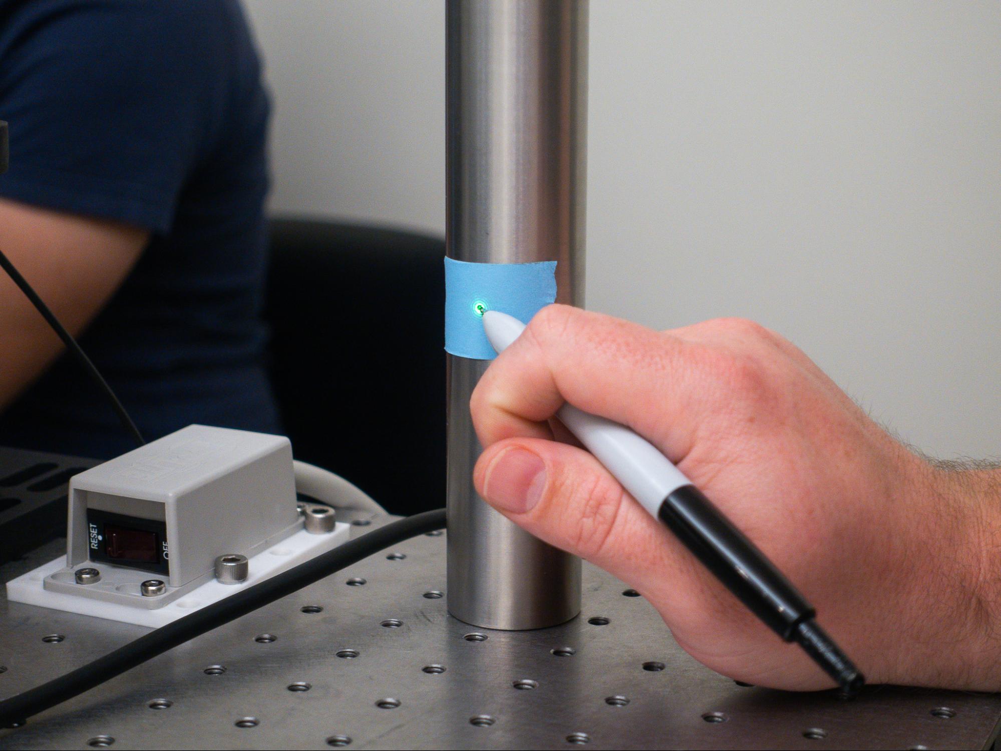
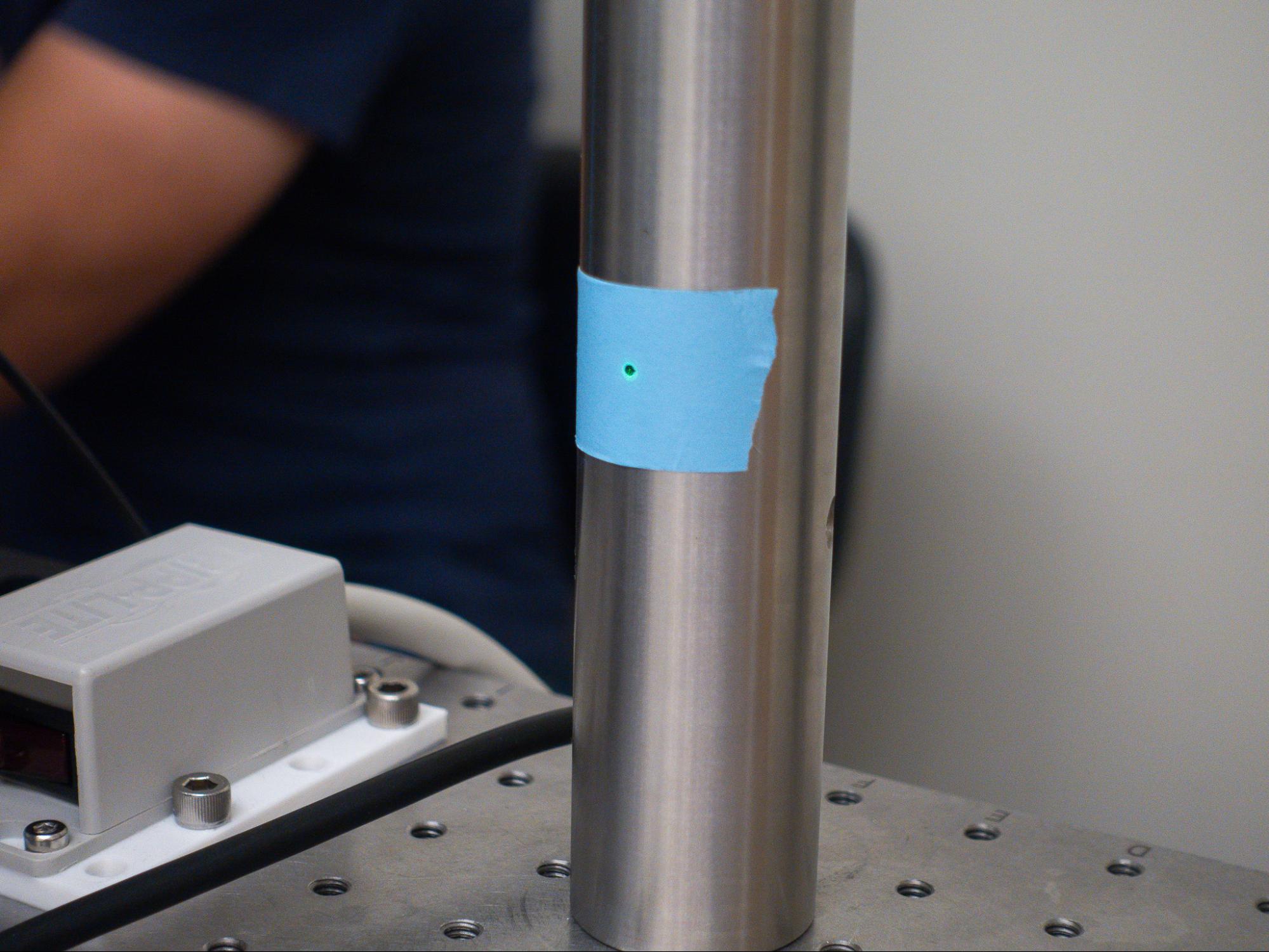
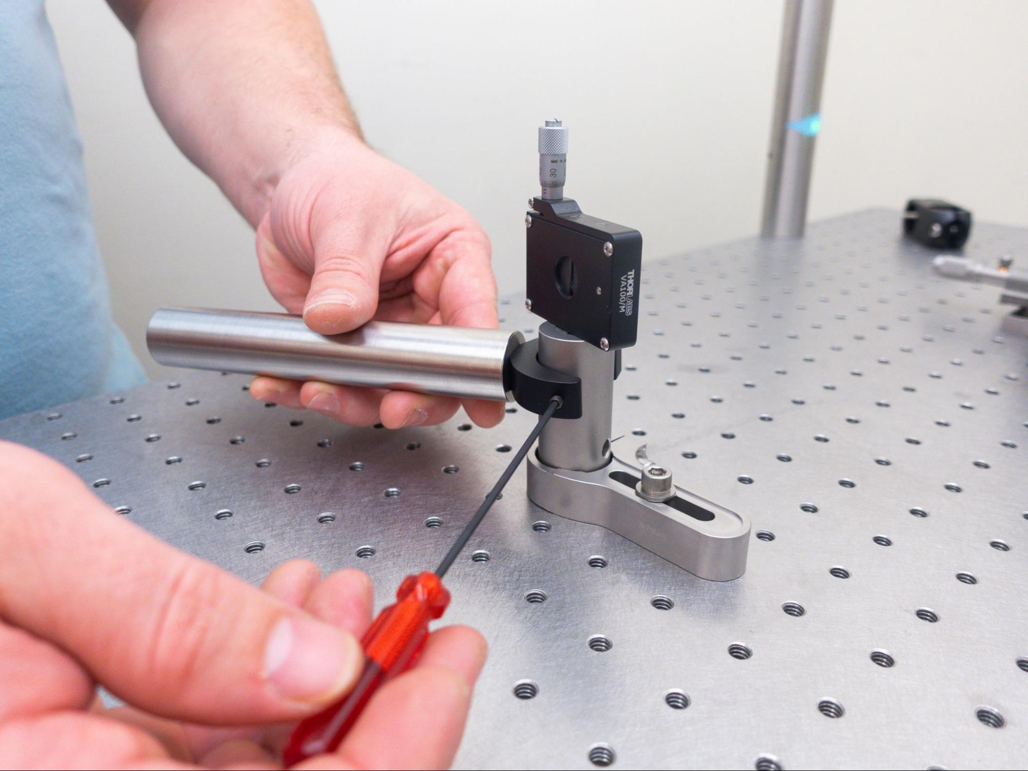
- Mount something rigid to the table that intersects with that reference point. For this guide, we are using a post.
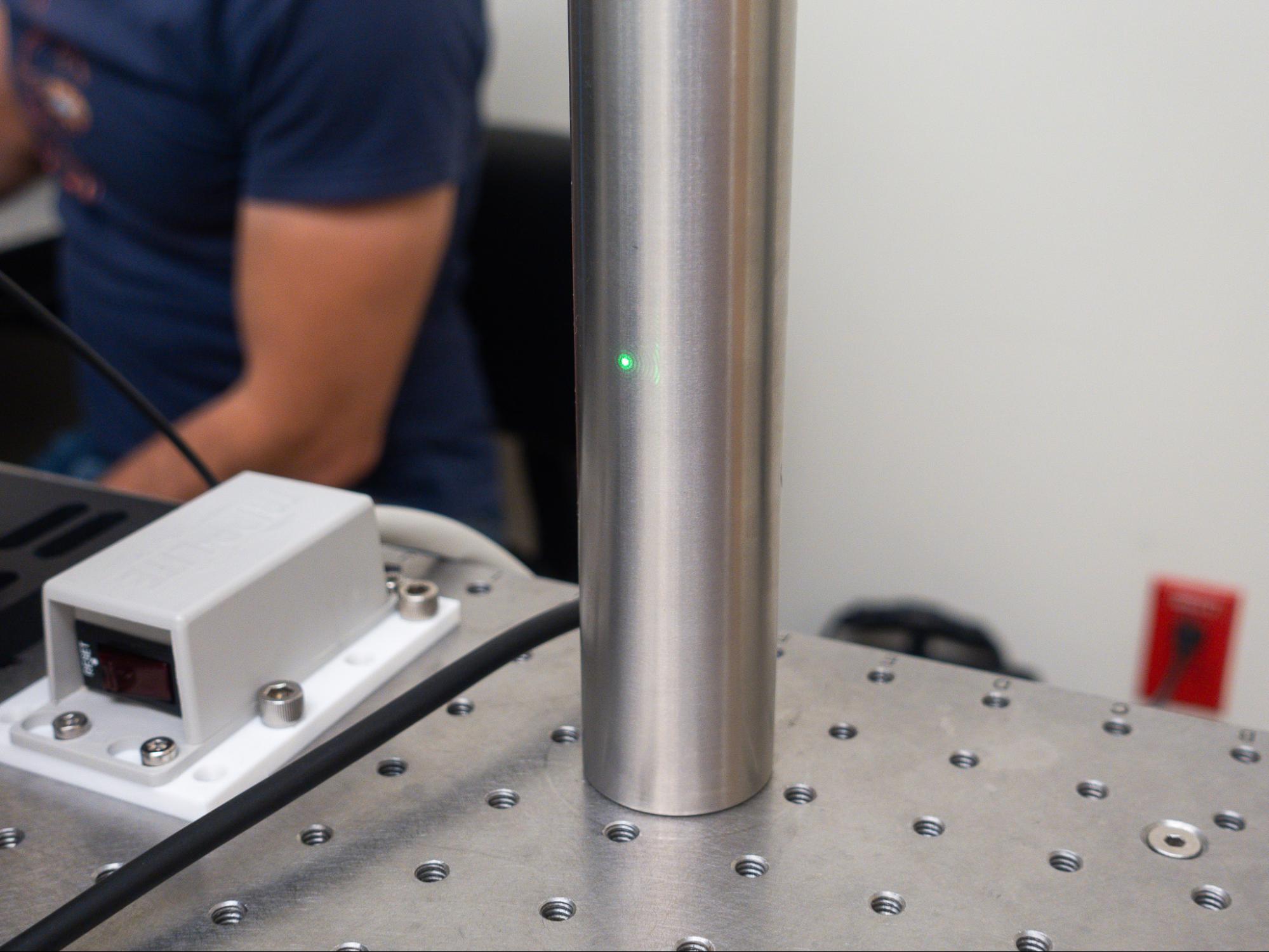
- Mark the point where your beam intersects rigidly or points to - this is your non-deflection point.
‼️Important Concept
Non-deflection point
A reference point indicating where the laser beam would pass through if no optic were present or if the optic were perfectly aligned. This is crucial because, after alignment, the beam should ideally intersect this point again, confirming proper optical positioning.
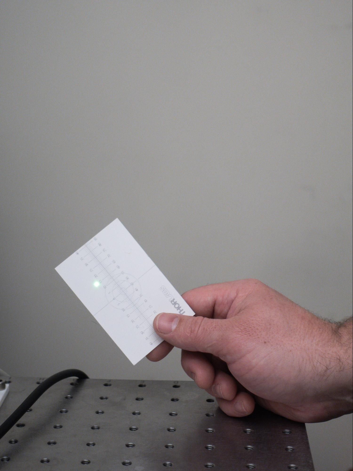
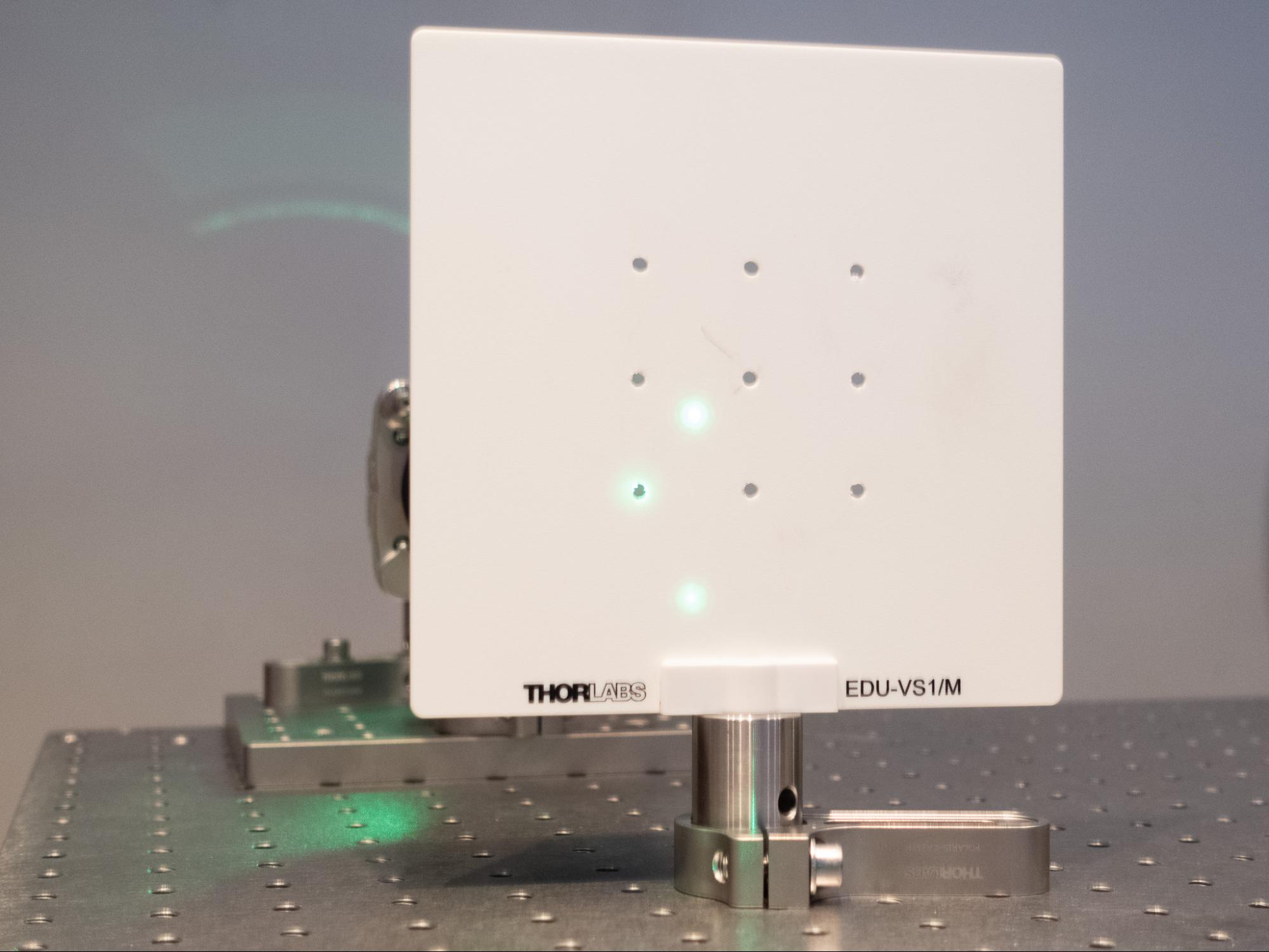
- Set up a surface and pinhole for your back reflections. In this tutorial, we used a screen mounted on a post and drilled holes into it. A simple card with a hole punched into it can also serve this purpose. To make small deviations more noticeable, it's best to place this point farther from the mount during the alignment process.
‼️Important Concept
Back reflections
The points where the laser beam reflects back toward the source after hitting an optical surface. These reflections help assess alignment accuracy – when they converge into a single point, it indicates that the optic is more precisely aligned. To make small deviations more noticeable, it's best to place this point farther from the optical mount.
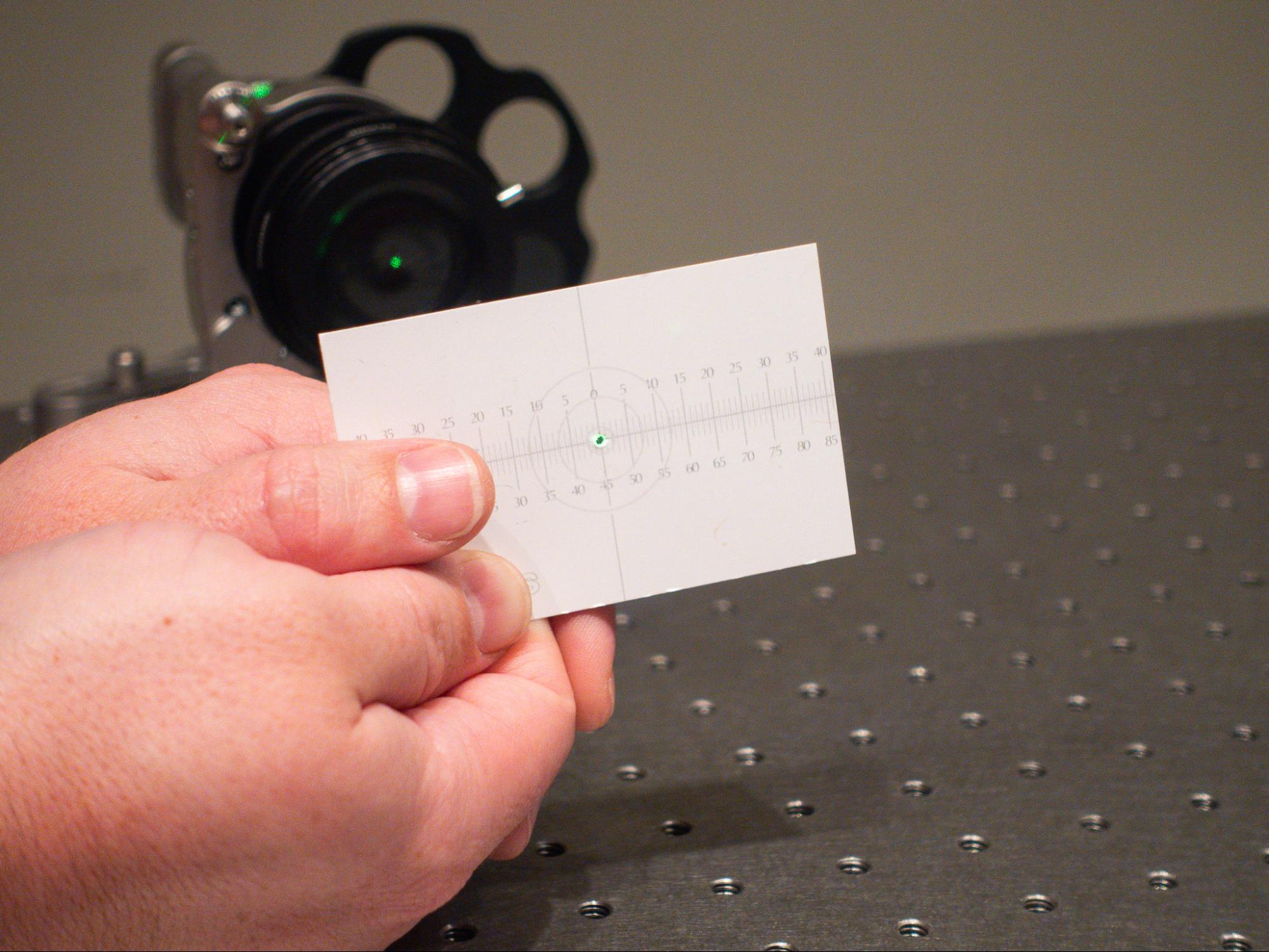
The goal as you align each optic is for the laser beam to hit the reference point, while the back reflections merge into a single point back into the pinhole. Those indicate proper optical positioning. The guide will walk through this process in greater detail later on in part four.
Phase 2: Mount the first optic on the table
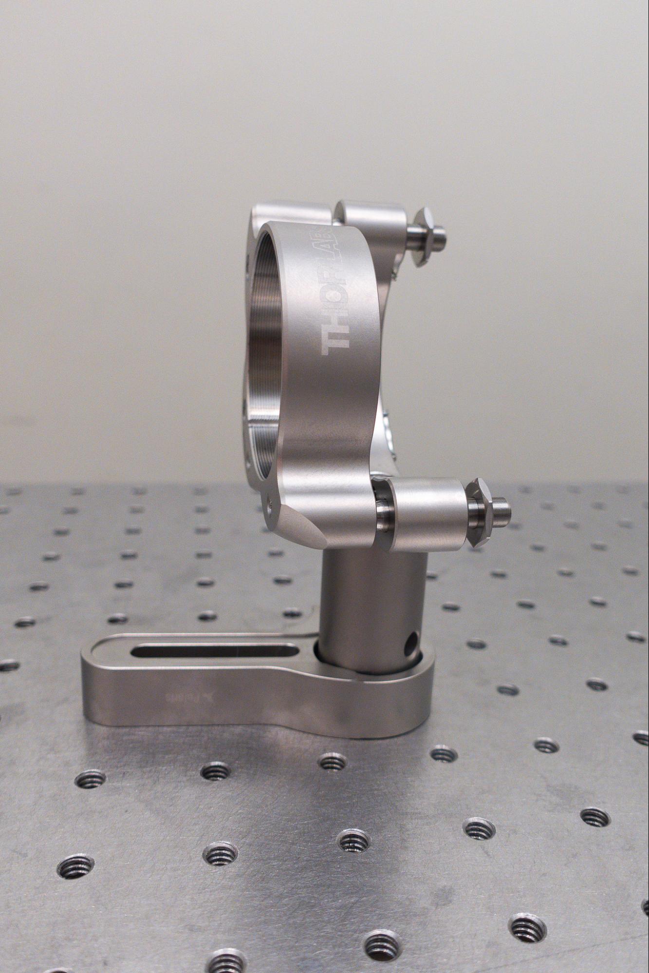
Here are the parts we will be using for the optical mount.
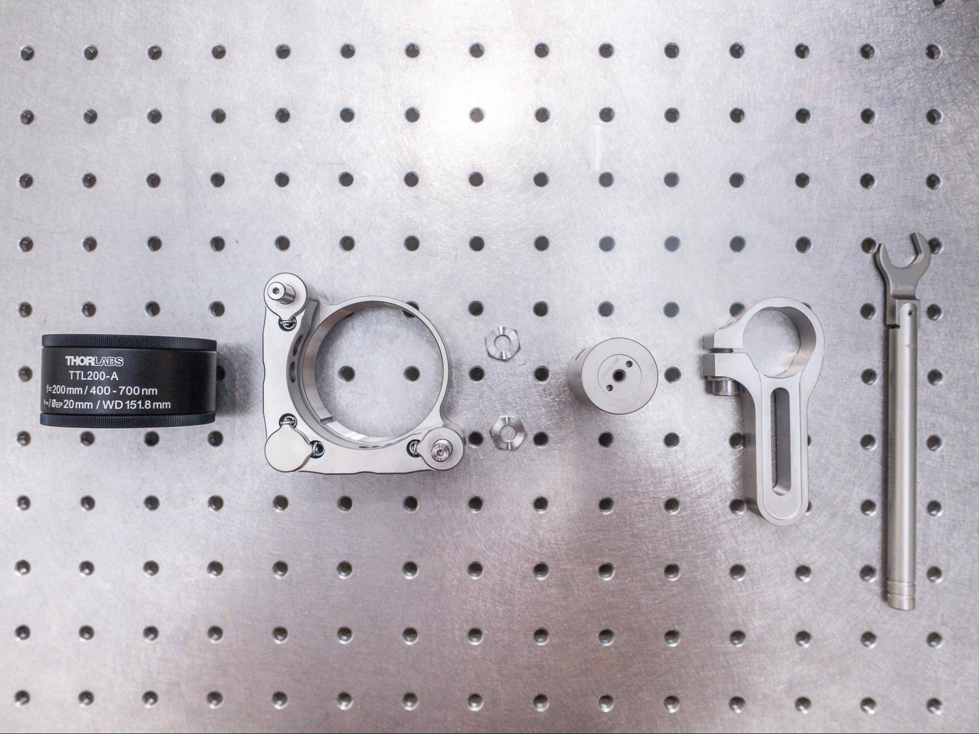
For this lesson, we are using a TTL200-A tube lens.
💡Tip
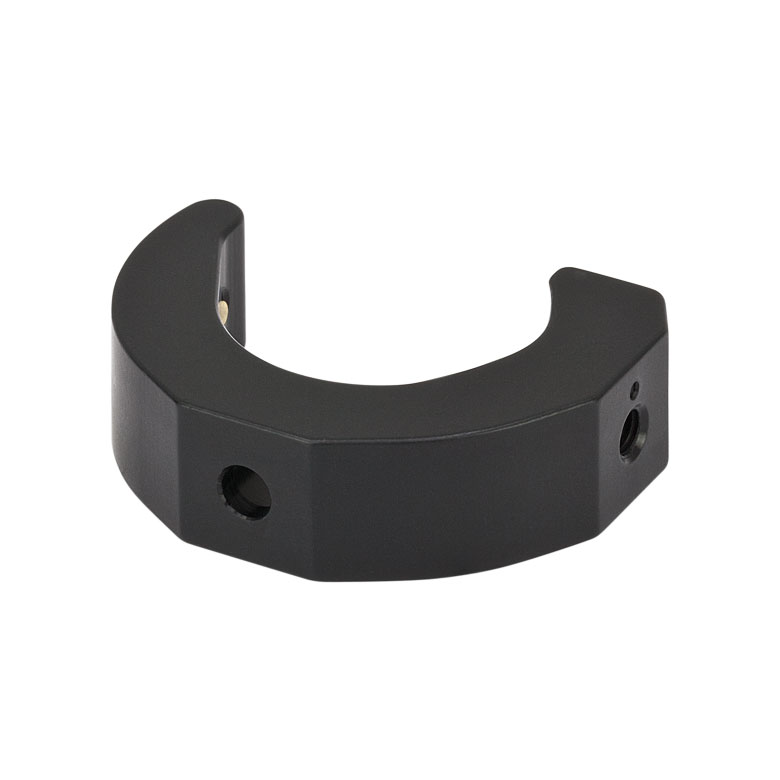
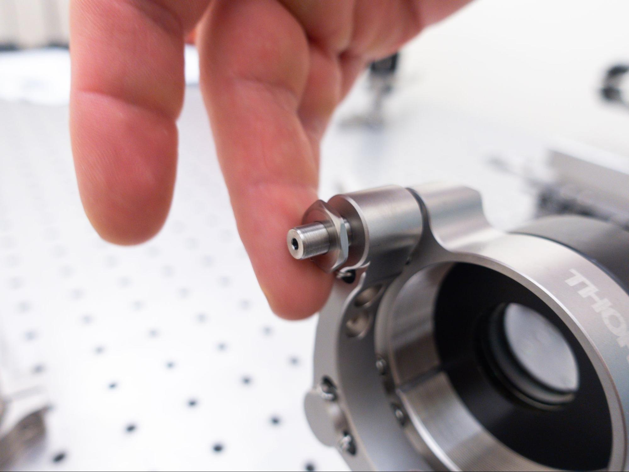
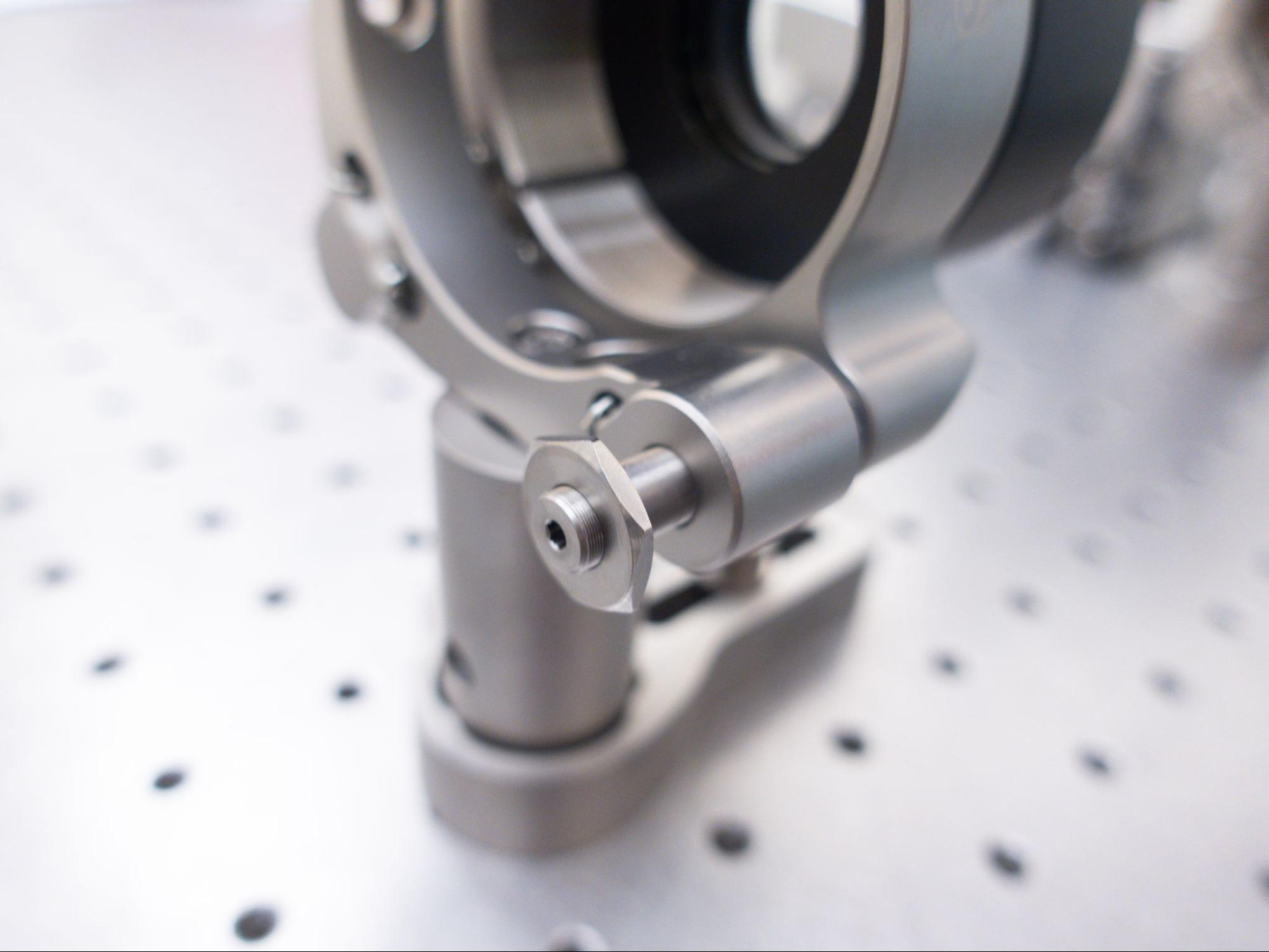
For this guide, we will connect the alignment crane directly to the Polaris mount.
If you are not using a Polaris mount, you can instead use a slip-on post clamp (e.g. RM1A/M) to connect the alignment crane to the optic's post.
- Use an M4 bolt to attach the mount (POLARIS-K2T2) to a post (PLS-P496/M).
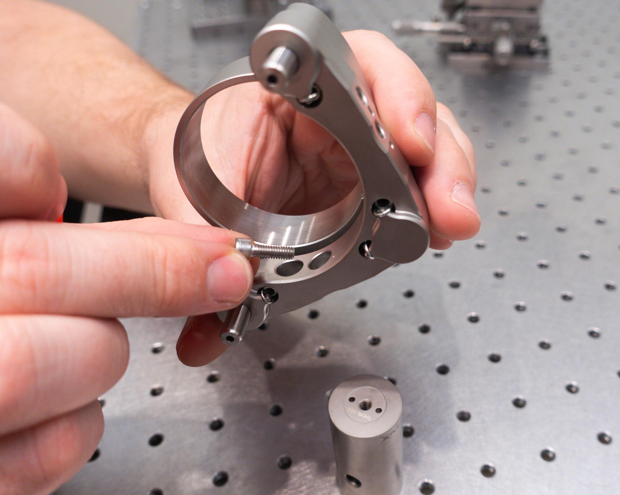
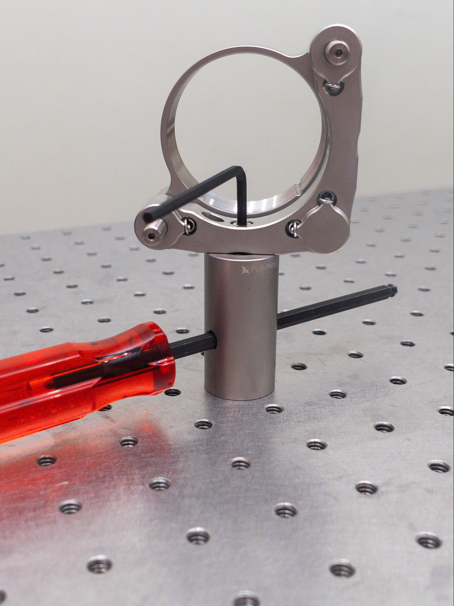
- Optionally add locking nuts (POLARIS-LN1) but don’t tighten all the way as we’ll make tip and tilt adjustments later.
- Put the post in the clamping arm (POLARIS-CA25/M).